NenuFAR is a large low-frequency radiotelescope, partly constructed and in commissioning, but already operational in « Early Science » phase. It is located in Nançay, 200 km south of Paris, France, in the Nançay Radioastronomy Observatory (NRO).
NenuFAR will gather at completion 1938 dual polarization antennas hierarchically distributed (Figure 1), of which 1064 are presently in operation.
It observes in the 10-85 MHz range, between the Earth’s ionospheric cutoff and the radio broadcast FM band. Most of the antennas are located within a core of diameter ~400 m, except for 6 groups of 19 antennas that will be at distances up to ~3 km.
The antennas are connected in parallel to several receivers, that allow the instrument to operate in 4 distinct modes (if needed simultaneously) :
The operating modes and data products are further described below.

See details and workshop material on https://nfm2024.sciencesconf.org/
After nearly 2 years of conducting observations in the “Early Science” phase, NenuFAR users gathered again for a workshop in Nançay on November 17-19, 2021. This workshop was dedicated to users and potential users, the opportunity to highlight results obtained from the various teams, and get the last up-to-date information about the instrument, data processing methods and facilities. Several practical sessions were organized around various projects and tools (Beamforming, pulsar, imaging, etc.) with NenuFAR data.
See details and workshop material on https://nenufaruser2021.sciencesconf.org/
NenuFAR will be a hopefully powerful but certainly complex instrument. In order to help the teams to prepare their activities, and to introduce observers to NenuFAR capacities, operating modes, and data, a a first NenuFAR workshop was held in Nançay on March 18-20, 2019.
See details of programme and attendance on https://nenufar2019.sciencesconf.org/
NenuFAR (New Extension in Nançay Upgrading LOFAR) is a new radioastronomy instrument, operating in the 10 – 85 MHz frequency band, which is in the last stages of its construction at the Station de Radioastronomie in Nançay (France). At completion, the instrument will be composed of a compact core of 96 mini-arrays of 19 antennas each plus 6 distant mini-arrays. Four operating modes will be implemented: standalone beamformer, standalone imager, Transient Buffer mode, and LOFAR super-station.
The scientific questions that can be adressed with NenuFAR are very diverse. A call has been issued early 2019 by the Comité Scientifique de NenuFAR (NenuFAR Scientific Committee, CSN) to the French community, plus foreign colleagues already involved in the project, for proposing Key Programmes (KP) using NenuFAR for the Early Science phase of the instrument. Key Programmes are structured teams led by a KP coordinator.
During the Early Science phase (July 2019 to December 2021), approximately 8000 hours of observations was available for KPs. The KP proposals included the various standalone operating modes of NenuFAR, or a combination of these modes. The LSS mode will ultimately be accessed through regular LOFAR calls.
Key Programmes have been originally proposed during the “Early Science” phase, gathering ~140 scientists (~50% French). Some programs evolved into “Long-Term” programs (LT), “Special” programs (SP) and “Regular” programs (RP).
The current list (as of Cycle #4) are listed below:
LT01: Cosmic Dawn (Koopmans et al.)
LT02: Exoplanets & Stars (Zarka et al.)
LT03: Pulsars (Theureau et al.)
LT04: Transients (Corbel et al.)
LT05: Fast Radio Bursts (Decoene et al.)
LT06: Planetary Lightning (Grießmeier et al.)
LT07: Joint Jupiter studies (Lamy et al.)
LT09: Cluster filament & Cosmic Magnetism (Bonnassieux et al.)
LT10: Radio recombination lines (Gusdorf et al.)
LT11: Sun (Briand, Morosan et al.)
LT12: Radio detection of Gamma showers (Dallier et al.)
LT13: SETI (Hellbourg et al.)
SP16: Formation of students (Girard et al.)
SP17: Radio amateur community (Maintoux et al.)
RP1A: Faraday Tomography in the 3C196 field (Bracco et al.)
RP1B: NenuFAR Low-Frequency Sky Survey (Girard et al.)
RP1C: Low-Frequency measurements on Cas A (Stanislavsky et al.)
Individuals wishing to join a KP should contact the CSN at nenufar-csn@listes.obs-nancay.fr (or via the contact form at the bottom of this page) who will transmit to the relevant KP P.I.
NenuFAR elementary antennas are crossed dipoles in inverted-V shape erected 1.6 m above a 3 m x 3 m ground plane (metallic grid). The antenna radiators are those developed for the LWA (USA). They are coupled to a custom-designed low noise preamplifier (developed in Nançay and Nantes) that ensures a relatively flat response across the entire 10-85 MHz band with a level of sky background several dB above the preamplifier noise at all frequencies. As a consequence, the sensitivity is sky-limited at all frequencies
The effective area of the instrument can be estimated by taking an effective area per dipole antenna Ae-dipole(l) » l2/3 and summing over the total number of antennas taking into account effective area overlaps for nearby antennas. Effective areas of the NenuFAR dipole are listed in Mini-arrays description (Table 1 in Mini-array section)
All dipoles across NenuFAR are (as for LOFAR) aligned at 45° from the meridian, either along the NE-SW direction (so-called NE or X dipoles) or along the NW-SE direction (so-called NW or Y dipoles). Combination of the two linearly polarized antenna signals allows to retrieve the full polarization of the incoming waves (4 Stokes parameters).


NenuFAR antennas (dipole + grid) have a quasi-isotropic response in the E-plane (perpendicular to the dipole) whereas the gain drops below an elevation ~20° in the H plane (containing the dipole).

Antenna response at 20 & 80 MHz in E and H planes.
NenuFAR antennas are grouped in hexagonal tiles of 19 crossed-dipoles, hereafter called Mini-Arrays (MA). The elementary mesh of the hexagon is an equilateral triangle of side length 5.5 m (inter-antenna distance within an MA), thus the net diameter of a MA is 25 m (Figure 4). Effective areas of the NenuFAR MA are listed in Table 1.
Within each MA, the signals of the 19 antennas (in each polarization) are combined through an analog phasing+summation system in order to form a steerable beam, that restricts the instantaneous Field of View (FoV) but provides higher sensitivity within it. The analog MA phasing system is formed of delay lines (switchable cables lengths) and thus essentially achromatic (the philosophy is the same as that of the square 4×4 tiles of LOFAR-HBA or MWA antennas, except that the hexagonal shape provides – for the same number of elementary delay lines, 10 per MA or per 4×4 tile – more effective area and order-6 grating beams of lower amplitude than the order-4 grating beams of 4×4 tiles). The delay lines are 7-bit systems of switchable cables lengths, permitting to point 27 = 128 discrete directions in the EW direction and 128 in the NS direction, hence a total of 128×128 = 16384 pointable directions in the sky, from horizons to zenith. After analog phasing+summation, each MA delivers two linearly polarized signals (NE and NW) via coaxial cables to the receivers.
The analog-phased steerable MA beam has a FWHM of order of λ/D with D~25 m, i.e. from ~8° at 85 MHz to ~46° at 15 MHz (Figure 5). Beam widths and instantaneous FoV at several frequencies are listed in Table 2.
|
Frequency (MHz) |
Wavelength (m) |
Ae-dipole (m2) |
Ae-Ma(m2) |
Ae-core (m2) |
Ae-all(m2) |
|
15 |
20. |
133 |
864 |
83001 |
88189 |
|
27 |
11.1 |
41 |
568 |
54612 |
58025 |
|
48 |
6.2 |
13 |
247 |
23750 |
25234 |
|
85 |
3.5 |
4 |
78 |
7574 |
8047 |
Table 1 : Effective areas Ae-dipole, Ae-MA, and Ae-core and Ae-all as a function of the frequency and wavelength.
|
Frequency (MHz) |
Wavelength (m) |
Ɵ-Ma (°) |
FoV-Ma (°2) |
Ɵ-core(°) |
Ɵ-all (’) |
|
15 |
20. |
46 |
1650 |
2.9 |
23 |
|
27 |
11.1 |
26 |
509 |
1.6 |
13 |
|
48 |
6.2 |
15 |
161 |
0.9 |
8 |
|
85 |
3.5 |
8 |
51 |
0.5 |
4 |
Table 2 : θMA and FoVMA are the beam width (FWHM) and instantaneous Field of View of NenuFAR’s MA as a function of the frequency and wavelength. θcore is the beam width (in beamformer mode) or angular resolution (in imager mode) of the core. θall is the angular resolution of the imager when all MA (core+remote) are used together.

Sketch of a Mini_array with 0° rotation

Analog-phased MA beams at 20 pointed to the zenith, in linear and dB scales. Cuts are shown at azimuth = 30°, where grating lobes are maximum.

Analog-phased MA beams at 80 MHz pointed to the zenith, in linear and dB scales. Cuts are shown at azimuth = 30°, where grating lobes are maximum.
NenuFAR’s antenna field consist of a dense core of 96 MA distributed within a disk of diameter ~400 m (Figure 6), plus 6 remote MA placed to the North-West, East/North-East and South of the core. The distribution of core MA ensures a quasi-perfect coverage of the uv plane for baselines between 25 m and 400 m, with Gaussian radial density and uniform azimuthal density, ensuring a Gaussian main beam in Beamformer mode (Figure 7). Remote MA are placed at distances in geometrical progression from the core up to ~3 km, resulting in a good coverage of the uv plane for baselines up to 3 km when combined with Earth rotation during a few hours (and multi-frequency synthesis if allowed by the scientific objectives).
The MA are rotated with respect to each other by angles multiple of 10°, in order to reduce the contribution of the side (and grating) lobes when MA signals are summed together. The antennas are back-rotated by the same angle to remain aligned throughout NenuFAR (same polarizations as LOFAR antennas). The rotation angle 0° corresponds to the 5 lines of antennas forming the hexagon all along the EW axis. Rotation angles from 0° to 350° are attributed, that will correspond to rotated local coordinates for each MA. However, due to the hexagonal symmetry, MA rotated by multiples of 60° have the same analog beam responses in the sky. For deconvolution of MA response during imaging, 6 rotation angles only need to be taken into account : 0°, 10°, 20°, 30°, 40°, 50°. All remote MA have the same rotation angle of 0°.
Figure 6 : Global MA distribution within NenuFAR, with deployment plan indicated.


The 96 MA x 2 polarizations analog signals from the core are split in order to feed simultaneously the LOFAR FR606 station backend and the main NenuFAR standalone receiver LaNewBa.
The outputs from the NenuFAR core MA are connected to the 96×2 LBL inputs (not used in LOFAR stations and thus available) of the LOFAR FR606 station, digitized, beamformed, and sent to the LOFAR central correlator as standard LOFAR signals. For the use of this LOFAR super station mode, please refer to the LOFAR astronomers page.
LaNewBa digitizes each of the 96×2 input signals at a sampling frequency of 200 MHz. The data streams are then channelized in subbands of 200 MHz/1024 = 195.3125 kHz bandwidth each. Beamforming then consists in coherently summing up the complex data streams from all MA for a given subband, polarization and direction (θ,φ) in the sky, after application of adequate phase shifts. A beamlet consists of one subband x 2 polarizations beamformed to one direction in the sky, i.e. it is defined by a triplet (fc,θ,φ) with fc the central frequency of the subband. The raw data stream corresponding to one beamlet consists of 195312 pairs of complex X (NE) and Y (SW) signals values per second. LaNewBa computes and delivers 768 such beamlets at any given time, that correspond to an instantaneous usable bandwidth of 150 MHz. These 768 beamlets can be distributed in (fc,θ,φ) as desired, from 2 beams (θ0,φ0) and (θ1,φ1) with 75 MHz bandwidth (i.e. the full band of the instrument) to 768 beams paving the analog beam (and possibly more) at a single frequency fc, through any intermediate scenario.
LaNewBa also computes and delivers in parallel 3 types of statistical data :
UnDySpuTed (Dynamic spectroscopy & pulsars modes)
The beamformed raw data from LaNewBa are distributed to several calculators via virtual local area network (VLAN). At present, the 2 identical CPU/GPU calculators UnDySPuTeD are operational. Each of them can process the raw data from 384 beamlets in one of 3 modes :
A raw waveform mode, in which the raw data stream (195312 pairs of complex X and Y signals values per second per beamlet) is written to disk.
A single mode can be used on each UnDySPuTeD calculator at a given time (possibly the same on both if 768 beamlets need to be processed simultaneously in the same mode).
Data products:
Lanes limitations:
NICKEL Correlator (Interferometric mode)
The NenuFAR correlator (the selection of which is ongoing) will fed by the signals from the 96 MA x 2 polarizations, digitized and channelized by LaNewBa, plus signals from the remote MA digitized and channelized directly at the foot of each MA and send to the correlator without passing through LaNewBa. The correlator will further channelize the signals and compute interferometric visibilities from all MA signals at a rate of one full set of cross-correlations per second within 75 MHz of bandwidth at 3 kHz resolution (384 subbands x 64 channels per subband = 24576 frequency channels). Note that this is the only receiver that take into account distant Mini-arrays.
Data products:
SETI (piggy-back receiver)
A dedicated SETI spectrograph with very high spectral resolution and possibly more advanced functionalities is under study. It will be connected to the VLAN and process in parallel the beamformed data delivered by LaNewBa, enabling piggyback SETI observations parallel to NenuFAR beamformed observations.
Transient Buffer Board (TBB)
The digitization boards of LaNewBa include transient buffers that store the last 5 seconds of waveform for each MA (or selected antenna within each MA) and each polarization. These buffers can be frozen and written to disk in response to an external trigger.
Report to Data Product for more details.
The NenuFAR receivers and data distribution are sketched below

NenuFAR pointing is done in 2 steps : (1) analog pointing of the MA and (2) digital pointing of the whole array.
Analog pointing is performed via the MA delay lines permitting to point a grid of 128×128 = 16384 directions in the sky. The grid step is <1° at zenith, corresponding to a gain variation <<1%, and increases toward the horizons (Figure 9). The working interval of NenuFAR corresponds to elevations ≥20°. Not all azimuths can be pointed for an elevation <20°. Furthermore, the instantaneous MA gain pattern is the product of the array term depending only on MA topology, by the antenna response. As a result, the real maximum of the MA gain pattern (when the MA does not point to the zenith) is located at a larger elevation than the maximum of the array term, this elevation is frequency-dependent. This is called the beam squint effect. In order to partly correct for it, the array term of the MA actually points to a pre-defined lower elevation than the desired one if the squint correction is enabled (a reference frequency must be specified). This lower elevation cannot be lower that 20°, due to the above limitation, so that the beam squint cannot be completely corrected for a target (desired) elevation ≤30°.
Digital pointing is continuous (grid-free). It is achieved by digital phasing of MA signals before summation (in beamformer mode) or correlation (in imager mode). Analog pointing, and digital pointing in beamformer mode, are locked on round multiples of 10 s, i.e. they occur at min:00 s, :10, :20, :30, :40, and :50 s. This ensures that any RFI or anomaly related to pointing can be easily identified and mitigated. Analog re-pointing of each MA occurs only if the nearest grid position has changed since the previous pointing. Not all MA need to be repointed together, due to their different rotation angles, implying that the grid of Figure 9 is rotated accordingly for each MA, so that the source trajectory through the grid is different for each different rotation angle. Digital re-pointing occurs every 10 s, and causes a gain variation ≤0.5% (≤0.02 dB) as a function of time.
Analog pointing is hardware-dependent (delay lines), which implies that a single pointing direction per MA is possible at any given time. Sub-arrays of NenuFAR can be defined with different analog pointing for each sub-array (the default mode is an analog-pointing of all MA in the same direction). On the contrary, digital pointing is software-defined per beamlet, so that up to 768 directions are in principle pointable simultaneously.
NenuFAR can work in transit or tracking mode. In tracking mode, the target can be defined by its coordinates (RA, DEC), its name (NenuFAR’s pointing is interfaced with IMCCE ephemeris service for solar system objects, and for the CDS/Simbad database for all other astronomical objects), or a list of coordinates in (Azimuth,Elevation, that follow the Geographic convention – AzElGeo – with origin of azimuths to the local North). When working in transit mode, the analog pointing is fixed to the nearest grid point and the digital pointing is directed exactly to the desired coordinates. When working in source tracking mode, the direction pointed at each re-pointing time (t = min:00, 10, …50 s) is the direction of the source at t+5 s, so that the source path crosses the centre of the beam in each consecutive 10 s interval.

Figure 9 : Grid of analog-pointable positions in local coordinates.
|
Collecting area (m2) |
Frequency (MHz) |
Current |
Complete |
|
Core only |
15 MHz |
69000 m2 |
83000 m2 |
|
50 MHz |
18000 m2 |
22000 m2 |
|
|
85 MHz |
6300 m2 |
7500 m2 |
|
|
Core + Distant Mini-arrays |
15 MHz |
72000 m2 |
88000 m2 |
|
50 MHz |
19000 m2 |
23000 m2 |
|
|
85 MHz |
6600 m2 |
8000 m2 |
Table 3: NenuFAR collecting area as a function of frequency and telescope completion
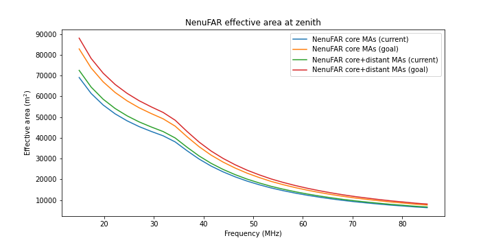
NenuFAR Effective area as a function of frequency
|
Angular resolution (°) |
Frequency (MHz) |
Current |
Complete |
|
Core only |
15 MHz |
2.39° |
2.11° |
|
50 MHz |
0.72° |
0.63° |
|
|
85 MHz |
25.2′ |
22.2′ |
|
|
Core + Distant Mini-arrays |
15 MHz |
21.5′ |
19.3′ |
|
50 MHz |
6.5′ |
5.8′ |
|
|
85 MHz |
3.8′ |
3.4′ |
Table 4: Maximum angular resolution as a function of frequency and telescope completion
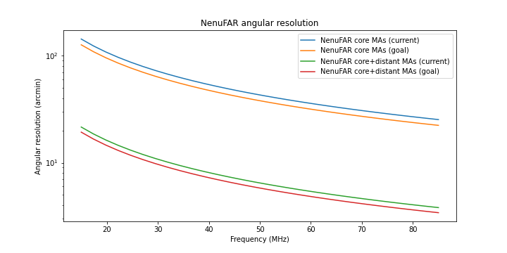
NenuFAR angular resolution as a function of frequency
|
Confusion noise (Jy) |
Frequency (MHz) |
Current |
Complete |
|
Core only |
15 MHz |
105.2 Jy |
86.9 Jy |
|
50 MHz |
7.1 Jy |
5.8 Jy |
|
|
85 MHz |
2.2 Jy |
1.8 Jy |
|
|
Core + Distant Mini-arrays |
15 MHz |
5.7 Jy |
4.8 Jy |
|
50 MHz |
383 mJy |
323 mJy |
|
|
85 MHz |
116 mJy |
98 mJy |
Table 5: Estimated confusion noise as a function of frequency and telescope completion
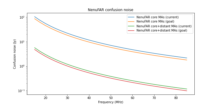
NenuFAR confusion noise as a function of frequency
The suite of NenuFAR receivers delivers/will deliver the following data products (names of data products are underlined.
Beamformer mode :
Transient Buffer mode :
Imager mode :
XST (Cross-Correlation STatistics) data (MS format) : LaNewBa computes interferometric visibilities from all MA signals at a rate of one full set of cross-correlations per second within 16 subbands (i.e. 3 MHz bandwidth). No channelization is performed within subbands (spectral resolution of 195 kHz). No pointing is applied (the phase centre is at the zenith). Data is recorded in FITS format. A python program nenums.py is run immediately after acquisition that converts the recorded data in MS format. During the conversion, the data can be rephased to any phase centre in the sky, and MS can simulate the tracking of a (RA, DEC) position, or transit (fixed pointing) at the zenith. The 16 subbands / s can sweep across NenuFAR’s frequency range. 1 MS is written per subband and per 2-hour slice of observation, padded with zeroes at time steps when the corresponding subband is not recorded (in case of frequency sweeping of the observed subbands during the observation). NenuFAR XST data are similar to XST data from LOFAR stations, except that the latter are recorded at the rate of one full set of cross-correlations per second per subband. XST data are recorded primarily for inter-MA phase calibration (permitting to build the calibration table to be loaded in LaNewBa that ensures fully coherent beamforming), but they can also be used for science requiring low spectral resolution (195 kHz) and narrow instantaneous bandwidth (3 MHz / s). The default use of XST data for imaging is deprecated since the default imaging receiver is NICKEL.
XST stream are now used in the NenuFAR-TV (snapshot image of the sky diaphragmed by the analog MA beam, at a rate of ~1 image / min).
LOFAR Super Station mode :
Other products :
|
BBS |
LOFAR’s Black Board Self-cal software |
LSS |
LOFAR Super Station |
|
BST |
Beamlet Statistics |
LWA |
Long Wavelength Array |
|
CASA |
Common Astronomy Software Applications package |
MA |
Mini-Array (of 19 crossed dipoles antennas) |
|
CDS |
Centre de Données de Strasbourg |
MS |
Measurement Set |
|
CPU |
Central Processing Unit |
MWA |
Murchison Widefield Array |
|
DM |
Dispersion Measure |
NDPPP |
LOFAR’s New Default Pre-Processing Pipeline |
|
FITS |
Flexible Image Transport System |
NenuFAR |
New extension in Nançay upgrading LOFAR |
|
FM |
Frequency Modulation radio broadcast band, 87-108 MHz |
NRO |
Nançay Radioastronomy Observatory |
|
FoV |
Field of View |
PRESTO |
PulsaR Exploration and Search TOolkit |
|
FWHM |
Full Width at Half-Maximum |
RA |
Right Ascension |
|
GPU |
Graphic Processing Unit |
RFI |
Radio Frequency Interference |
|
GSM |
Global Sky Model |
SETI |
Search for Extra Terrestrial Intelligence |
|
HBA |
High Band Antennas from LOFAR (110-250 MHz) |
SNR |
Signal to Noise Ratio |
|
IMCCE |
Institut de Mécanique Céleste et de Calcul des Éphémérides (Observatoire de Paris) |
SST |
Spectral STatistics |
|
LaNewBa |
LSS advanced New Backend |
TBB |
Transient Buffer Boards |
|
LBA |
Low Band Antennas from LOFAR (30-80 MHz, down to 10 MHz with reduced sensitivity) |
UnDySPuTeD |
Unified Dynamic Spectrum Pulsar and Time Domain receiver |
|
LBL |
Low Band Low antenna inputs unused in LOFAR stations |
VLAN |
Virtual local area network |
|
LOFAR |
LOw Frequency ARray |
XST |
Cross(X)-correlation STatistics |